
Do you know overlay welded tubesheet?
During the heat exchanger design phase, the choice of Tubesheet material is a core decision that determines both equipment cost and reliability. Overlay welded tubesheets are not suitable for all scenarios; rather, they represent an optimized solution under specific service conditions, situated between solid corrosion-resistant alloy tubesheets and plain carbon steel tubesheets.
Trade-off Between Media Corrosivity and Material Cost
When the tube-side or shell-side media are highly corrosive (such as sour crude oil, acidic gases, acetic acid, seawater, etc.), the tubesheet requires corrosion resistance. Two mainstream solutions are available:
| Advantages | Disadvantages | |
|---|---|---|
| Solid corrosion-resistant alloy tubesheet (stainless steel, nickel-based alloy, titanium) | Optimal corrosion resistance, simple structure, no risk of detachment | Extremely high material cost, difficult machining, long delivery lead time |
| Overlay welded tubesheet (carbon steel/low-alloy steel base + corrosion-resistant overlay) | Base material provides strength, overlay provides corrosion resistance, lower overall cost | Complex manufacturing process, high requirements for welding quality |
The cost advantage of overlay welded tubesheets is particularly pronounced for large-diameter, thick-wall tubesheets. For example, for a tubesheet with a diameter of 2 meters and thickness of 150 mm, a solid Inconel 625 construction would cost several million RMB in material alone; whereas using an SA516 Gr.70 base with Inconel 625 overlay welding can reduce material cost by over 50%, while the base material’s strength and toughness fully meet pressure vessel design requirements.
Combining Strength and Corrosion Resistance Under High Temperature and High Pressure
Certain heat exchangers face the dual challenge of high pressure and severe corrosion. Solid corrosion-resistant alloys (such as austenitic stainless steel) have relatively low strength at elevated temperatures, potentially requiring a significant increase in tubesheet thickness; low-alloy steels (such as 15CrMo, SA387 Gr.11), on the other hand, offer excellent high-temperature strength but lack corrosion resistance. In such cases, overlay welded tubesheets become the ideal choice: the base material is selected for its high-temperature strength (chrome-molybdenum steel), while the overlay is chosen for its high-temperature corrosion resistance (nickel-based alloy or austenitic stainless steel), achieving a division of labor where “strength + corrosion resistance” are handled by separate materials.
Mitigating Stress Corrosion Cracking Risks
For certain sensitive media (such as wet hydrogen sulfide or chloride-containing aqueous solutions), solid austenitic stainless steel tubesheets carry a risk of stress corrosion cracking (SCC) . In contrast, the overlay layer can be made from materials with superior SCC resistance (such as duplex stainless steel or Inconel 625), while the carbon steel or low-alloy steel base material is inherently insensitive to SCC. This dissimilar material combination can effectively reduce the overall SCC risk of the equipment.
Compatibility Requirements for Tube-to-Tubesheet Welding
The connection between heat exchanger tubes and the tubesheet is typically achieved by welding or expanding. If the tubes are made of stainless steel or nickel-based alloy while the tubesheet is solid carbon steel, the tube-to-tubesheet weld becomes a dissimilar metal weld, introducing a series of issues such as dilution control, differences in thermal expansion coefficients, and galvanic corrosion. Overlay welded tubesheets address this by depositing a corrosion-resistant overlay on the tubesheet face that is identical or compatible with the tube material, converting the tube-to-tubesheet weld into a similar material weld, which significantly improves weld quality and reliability.
Typical Application Scenarios
In practical engineering, the following service conditions typically favor overlay welded tubesheets:
Refinery hydroprocessing units
High-pressure heat exchanger tubesheets, base material 12Cr2Mo1V (chrome-molybdenum steel), overlay E309L + E347L or Inconel 625
Acetic acid/acrylic acid plants
Tubesheet base material 16Mn or SA516, overlay C276 or C22 nickel-based alloy
Fertilizer plants (urea)
Tubesheet base material carbon steel, overlay urea-grade 316L
Offshore platforms/seawater coolers
Tubesheet base material carbon steel, overlay duplex stainless steel or nickel-based alloy
Situations Where Overlay Welding Is Not Suitable
Overlay welded tubesheets are not a universal solution and should be used with caution or avoided in the following cases:
- Tubesheet diameter is too small (e.g., <500 mm): the cost difference between overlay welding and solid corrosion-resistant alloy is negligible, but the manufacturing cycle is longer
- Excessive overlay thickness requirement (e.g., >10 mm): multiple overlay passes increase cracking risk and manufacturing difficulty
- Extremely low operating temperature (e.g., below -100°C): the low-temperature toughness compatibility between base and overlay must be evaluated
- Strongly oxidizing media with erosion-corrosion: localized thinning of the overlay layer could accelerate failure
Why Is Strip the Preferred Form as Overlay Raw Material?
Once the decision to adopt overlay welding is made, the selection of raw material becomes the first step in process development. For large-area overlay welding of heat exchanger tubesheets, the most commonly used form of raw material is strip, technically referred to as welding strip or strip electrode.
Process Advantages of Strip Submerged Arc Overlay Welding
Tubesheet overlay welding primarily employs the strip submerged arc welding (SAW) process, which uses a flat, coiled strip as the consumable. This choice is based on the following engineering considerations:
High productivity
The width of the strip is significantly greater than that of conventional welding wire. Common specifications include 30 mm, 50 mm, 60 mm, 75 mm, 90 mm, etc. The single-pass coverage area is large, and deposition efficiency is extremely high, making it suitable for mass production of large-diameter tubesheets.
Low dilution rate
Compared to wire processes, strip overlay welding produces shallower and more uniform penetration. The dilution rate of base material into the overlay is typically controlled below 10%–15%, better ensuring the composition and performance of the corrosion-resistant layer.
High-quality surface finish
When used with specialized agglomerated fluxes, strip overlay welding produces a smooth, flat bead surface with smooth edge transitions and excellent slag detachability, facilitating control over overlay thickness uniformity and reducing subsequent machining allowances.
Typical Specifications and Materials of Welding Strip
Thickness: Typically 0.4 mm or 0.5 mm.
Width: Depending on tubesheet size and overlay welding equipment, common widths include 30 mm, 50 mm, 60 mm, 75 mm, 90 mm, etc.
Materials:
- Stainless steel series: Such as E347L, E309L, E316L, used for corrosion-resistant layers in general chemical media. This is the most common combination for heat exchanger tubesheets. Typically, a dual-layer overlay is applied: the first layer E309L serves as a buffer layer (absorbing higher dilution), and the second layer E347L or E316L serves as the corrosion-resistant layer.
- Nickel-based alloy series: Such as Inconel 625, C276, used for high-temperature, highly corrosive media (such as wet hydrogen sulfide, high-temperature acetic acid).
Alternative Forms of Overlay Materials
Although strip is the mainstream choice for large-area overlay welding, other material forms are used in different applications or locations:
- Wire: Used for TIG (GTAW) or MIG (GMAW) processes, typically for overlay welding on tubesheet edge bevels, small-area repair welding, or for certain special alloys (such as cobalt-based alloys).
- Powder: Used for plasma transferred arc (PTA) welding. This process produces a well-formed hardfacing layer and is often used for high-wear resistance or precision dimensional overlay, though it is less common in standard heat exchanger tubesheet manufacturing.
Process Sequence: Overlay Welding First, Then Drilling
The manufacturing sequence for overlay welded tubesheets is one of the most frequently asked questions by customers and inspectors, and it is a critical factor in determining product quality. The standard answer is: overlay welding first, then drilling.
Ensuring Overlay Integrity and Uniformity
When overlay welding is performed first, the tubesheet surface is a complete plane, allowing welding heat input to be uniformly distributed. The overlay can continuously cover the entire face and bevel areas. If drilling is performed first followed by overlay welding, the hole edges become discontinuities in the welding path, making it easy for defects such as lack of fusion, undercut, and localized overheating deformation to occur, compromising the continuity of the corrosion-resistant layer. This issue is especially problematic in the narrow areas between holes.
Avoiding the Impact of Welding Deformation on Hole Position Accuracy
The overlay welding process generates significant welding deformation, particularly for large-diameter, thin-walled tubesheets. The thermal input from welding causes the base material to expand and contract, resulting in considerable distortion. If holes are drilled before overlay welding, this deformation will cause hole position shifts and pitch deviations that cannot be corrected later. By performing overlay welding first and then drilling, all dimensional accuracy is ensured during the final machining stage, resulting in accurate hole positions and controlled pitch.
Preventing Lamellar Tearing Risk
When the base material is high-strength low-alloy steel (such as 16Mn, SA516 Gr.70, etc.) and the overlay is stainless steel or nickel-based alloy, the welding thermal cycle generates high restraint stresses in the base material. If holes are drilled first, the hole edges become stress concentration points, significantly increasing the risk of lamellar tearing in the base material. Overlay welding first avoids this risk—because during welding, the base material is continuous with no free edges to serve as crack initiation sites.
Ensuring Corrosion Resistance Continuity Along the Tube Hole Bore
During drilling, the drill bit passes through both the overlay and base material in a single operation, resulting in a tube hole bore that presents a complete overlay-base interface. For subsequent tube-to-tubesheet welding or expanding, the hole interior is free from overlay interruptions or defects, ensuring reliable joint quality. If holes are drilled before overlay welding, it is difficult to ensure uniform overlay coverage along the hole walls, and the thermal cycles from overlay welding will affect the dimensional accuracy of the pre-machined holes.
Control of Key Overlay Welding Process Parameters
The formulation of the overlay welding process is centered on controlling dilution rate, heat-affected zone, and welding deformation while ensuring the corrosion resistance performance of the overlay layer.
Overlay Welding Methods and Equipment Selection
| Method | Characteristics | Applicable Scenarios |
|---|---|---|
| Strip submerged arc welding (SAW) | High deposition efficiency, low dilution, smooth overlay surface | Large-diameter tubesheets, mass production |
| Tungsten inert gas welding (TIG/GTAW) | Very low dilution (<10%), high quality control | Small-diameter tubesheets, bevel areas, nickel-based alloy overlay |
| Shielded metal arc welding (SMAW) | High flexibility, simple equipment | Field repair welding, small batches |
For large heat exchanger tubesheets, strip submerged arc overlay welding is recommended as the primary process. A dual-layer overlay design is typically adopted: the first layer is a buffer layer (higher dilution, used to mitigate alloy dilution of the corrosion-resistant layer by the base material), and the second layer is the corrosion-resistant layer (composition meeting corrosion resistance requirements).
Dilution Rate Control
Dilution rate is a critical parameter in the overlay welding process. Excessively high dilution causes excessive contamination of the corrosion-resistant layer with base material elements (such as Fe), reducing corrosion resistance; excessively low dilution may compromise bond strength. Measures to control dilution include:
- Using strip overlay welding with appropriate welding parameters (voltage, current, travel speed)
- Applying a buffer layer, where the first overlay layer uses high-chromium-nickel material to accommodate higher dilution
- Controlling interpass temperature to avoid overheating
- Optimizing overlay direction and bead overlap design
Typically, the surface composition of the overlay layer (corrosion-resistant layer) must meet standard requirements. This is usually verified through chemical analysis of test coupons from actual overlay welding trials.
Post-Weld Heat Treatment and the Role of Sand Bed
Overlay welded tubesheets typically require post-weld heat treatment (PWHT), especially when the base material is low-alloy steel (such as 15CrMo, SA387 Gr.11, etc.) or when thickness is substantial. In this stage, sand (silica sand) plays an indispensable role.
Purposes of Heat Treatment
- Eliminate residual welding stresses in the overlay and base material
- Soften the heat-affected zone and reduce hardness
- Prevent stress corrosion cracking during subsequent drilling or in service
Sand Bed Heat Treatment: Preventing High-Temperature Deformation
During PWHT (typically carried out at 650–750°C), the yield strength of steel decreases dramatically. Large tubesheets can weigh tens of tons; if placed directly on the steel hearth of the heat treatment furnace, they are prone to sagging, warping, or permanent central concavity under their own weight.
Functions of the sand bed:
Uniform support
The tubesheet is placed on a leveled sand bed. Silica sand, with its excellent flowability, adapts to the irregular contours of the tubesheet underside (such as bosses or grooves) at high temperature, providing uniform, continuous surface support. This avoids point or line support from steel shims, which can cause localized stress concentration and deformation.
Uniform temperature field
Silica sand has a high heat capacity, absorbing and storing heat. During heating, the sand slowly transfers heat to the tubesheet bottom, ensuring more uniform heating of the upper and lower surfaces and preventing temperature differences and thermal stresses caused by hot furnace gases directly impinging on the tubesheet bottom edge.
Oxidation mitigation
The dense sand layer partially isolates the oxidizing furnace atmosphere, slowing the formation of oxide scale on the tubesheet underside.
Operational Considerations in Practice
- Sand bed preparation: A layer of dry silica sand (typically 100–300 mm thick) is spread evenly on the furnace hearth.
- Critical note: The sand must be dry. Any moisture present will vaporize during heating, potentially leading to localized hydrogen pick-up by the tubesheet or causing cracking.
- Tubesheet placement: Shims (made of heat-resistant steel) may be placed on the sand bed with the tubesheet on top, or the tubesheet may be partially embedded in the sand.
- Heat treatment execution: Strict adherence to the heating rate, holding temperature, and cooling rate specified in the Procedure Qualification Record (PQR).
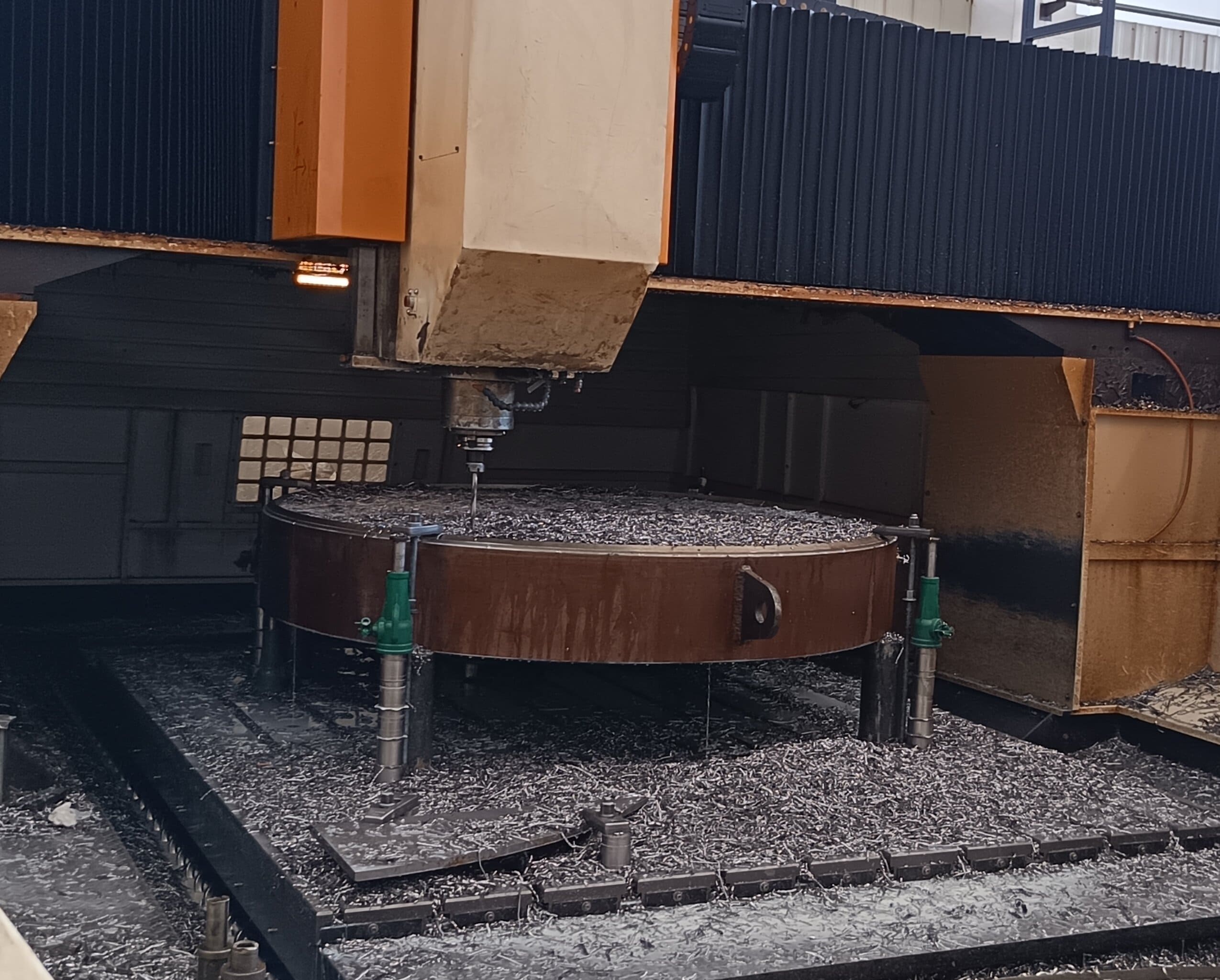
Drilling Operation: The Final Accuracy Assurance
After overlay welding and heat treatment, the drilling operation is the critical step that ensures the quality of the tube-to-tubesheet connection.
Drilling Process Requirements
- Drilling sequence: Typically a sequence of pilot drilling, reaming, and final sizing (e.g., boring or reaming) is used to ensure bore wall roughness and dimensional accuracy.
- Adequate cooling: Overlay materials (especially stainless steel and nickel-based alloys) have poor thermal conductivity and are prone to work hardening during drilling. Ample cooling and sharp carbide tooling are essential.
- Bore wall quality: The bore must be free of steps, burrs, and scratches. For tube holes requiring expansion, bore wall roughness requirements are more stringent (typically Ra ≤ 6.3 μm).
Quality Control at the Tube Hole and Overlay Interface
After drilling, the tube hole bore reveals the overlay-base interface. This interface must be inspected for defects such as lack of fusion, slag inclusions, or delamination. Common inspection methods include penetrant testing (PT) and ultrasonic testing (UT) .
FAQ
How to Ensure the Overlay Does Not Delaminate or Spall?
Strict control of preheat (when required) and interpass temperatures
Use of a buffer layer for dissimilar metal overlay welding (e.g., carbon steel base + nickel-based overlay)
100% penetrant testing (PT) and ultrasonic testing (UT) of the overlay after welding; shear strength testing may be added to verify bond strength where necessary
How to Control Tubesheet Flatness and Hole Pitch Accuracy?
Sufficient machining allowance (typically 3–5 mm per side) is reserved during the overlay welding stage
Post-weld heat treatment is performed to relieve welding stresses
Final drilling is performed on CNC gantry drilling machines, using the post-overlay machined surface as the datum to ensure hole position accuracy complies with standard requirements (such as GB/T 151 or ASME VIII-1)
How to Ensure Uniform Overlay Thickness and Satisfy Corrosion Allowance Requirements?
During overlay welding, thickness gauges or ultrasonic thickness meters are used to monitor overlay thickness in real time
Overlay thickness is generally required to be not less than 3 mm (or as specified on the drawing), and the final thickness after machining must meet the design corrosion allowance
Extra overlay thickness is applied in critical areas of the tubesheet (such as bevels, narrow zones between holes) to prevent thickness deficiency after machining
Overlay Welded Tubesheet Manufacturing Cycles Are Long; How to Ensure Delivery Schedules?
Plan heat treatment and machining subcontracting resources in advance
Use efficient processes such as strip submerged arc overlay welding to reduce welding time
Coordinate with the customer to optimize the number of heat treatment cycles (e.g., combining post-overlay heat treatment with final stress-relieving heat treatment) where quality requirements permit